Assembly
⚠️ IMPORTANT: Servo horns must be in a "+" orientation on every joint except Joint 4, which requires an "X" orientation during assembly.
Base and First Motor
- Insert and Mount First Motor:
- Attach Follower Clamp base to base by screwing in the follower base retainers with M2.5 screws.
- Attach servo driver mount to the back of the base and the servo driver on the mount with M2.5 screws.
- Insert the wire securely into the first motor.
- Place the servo horn in + Position and screw the Shoulder Pan link in zero position and driving horn to the motor with M3 bolts.
- Insert the shoulder pan pin under the shoulder pan link.
- Place the motor inside the base and secure it using four M2.5 screws (two from the top and two from the bottom).
- Insert the shoulder pan retainer and fasten it with one M2.5 screw on each side.
- Route the wire to robot's back where servo bus is mounted and insert the wire into the bus.
Second Motor and Upper Arm
- Install and Connect Second Motor:
- Slide the second motor into the shoulder pan from the top and connect the wire to the other connector on the servo bus.
- Secure the second motor with four M2.5 screws and attach both motor horns in a + position, tightening driving horn with an M3 bolt.
- Install the shoulder lift in zero position to second motor using four M3 bolts on each side.
Third Motor and Elbow
- Mount Third Motor and Attach Forearm:
- Route the wire from motor 2 and connect it to motor 3.
- Secure motor 3 using four M2.5 screws and attach both motor horns in a + position, securing driving horn with an M3 bolt.
- Attach the elbow in zero position using four M3 bolts on each side.
Fourth and Fifth Motor with Wrist 1
- Install Motor 4:
- Insert motor 4, connect it to motor 3's cable.
- Secure motor 4 with four M2.5 screws and attach both motor horns in X position, securing driving horn with an M3 bolt.
- Install Motor 5 onto Wrist 1:
- Insert motor 5 into the wrist_1, secure it with four M2.5 screws.
- Mount Wrist 1 onto Motor 4:
- Mount the wrist_1 in zero position onto motor 4 with four M3 bolts on both sides and connect motor 5 to motor 4.
- Attach driving horn to motor 5 in a + position and secure it with an M3 bolt.
Wrist 2 and Gripper
- Install Wrist 2 and Gripper:
- Attach the wrist_2 to motor 5 and insert the gripper motor.
- Connect the second wire from motor 5 to the gripper motor.
- Attach the motor horns in + position, securing driving horn with an M3 bolt, then fasten the gripper using four M3 bolts on each side.
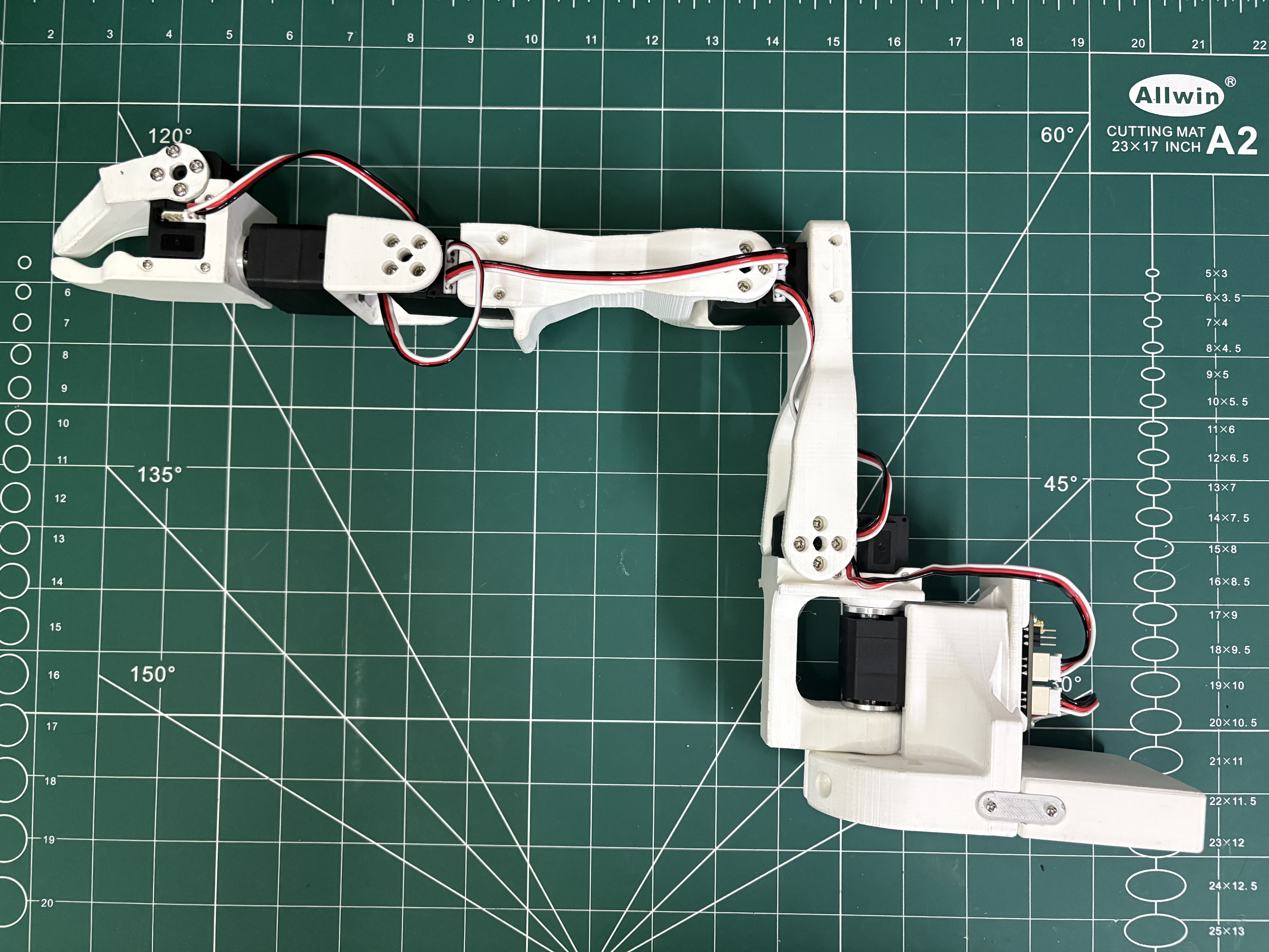
Assembly complete!
Your finished Giraffe follower arm should look like this: