Prechecks
Tools Required
- Screwdriver (PH1 and PH2 Bits needed)
- Soldering Iron and Wire
- Flush Cutter
Printing The Parts
A variety of 3D printers can be used to print the necessary parts for the arm. Follow these steps for optimal printing results.
1. Select A Printer
When choosing a printer, keep the following recommended specifications in mind. While other printers may work, these specifications are a good starting point:
- Layer Height: Minimum 0.2mm
- Material: PLA+, ABS, PETG, or other durable plastics
- Nozzle Diameter: Maximum 0.4mm
- Infill Density: Approximately 30%
- Suggested Printers: Prusa Mini+, Bambu P1, Ender3, and similar models
2. Prepare The Printer
-
Materials Needed:
- Standard Glue Stick
- Putty Knife
-
Setup and Printing Process:
- Calibrate the printer and level the print bed following your printer’s specific instructions.
- Clean the print bed, removing any dust or grease. If you use water or other cleaning agents, ensure the bed is fully dry.
- Apply a thin, even layer of glue to the print area. Avoid uneven application or clumps.
- Load the printer filament according to the printer's guidelines.
- Adjust the printer settings to match the recommended specifications listed above.
- Verify the file format, select files from the hardware folder, and begin printing.
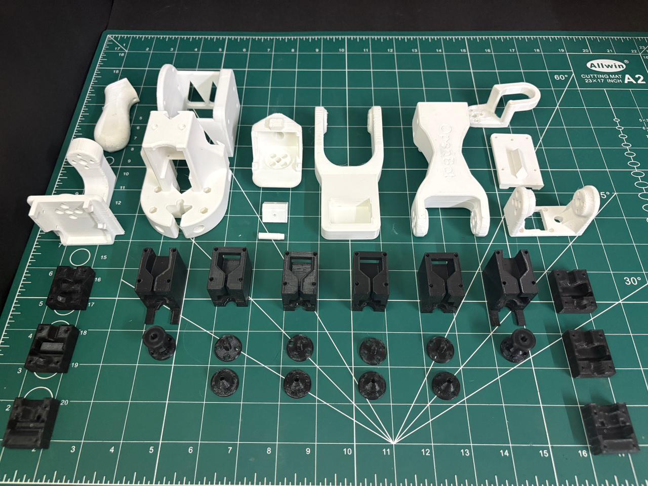
3. Print The Parts
Print one of each part found in /CAD/STL/common/ and /CAD/STL/leader/. The files are organized as follows:
Leader Parts
- base
- servo_driver_mount
- shoulder_pan
- shoulder_pan_retainer
- shoulder_pan_pin
- shoulder_lift
- elbow
- wrist_1
- as5600_servo_1
- as5600_servo_2
- leader_clamp_base
- leader_wrist_2
- leader_handle
- leader_gripper_finger
Note on Joint 5 & 6:
Joints 5 and 6 use the “AS5600_Servo_2” variant. This variant has a different design and no idle shaft.
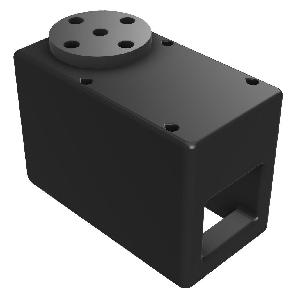
Servo 1
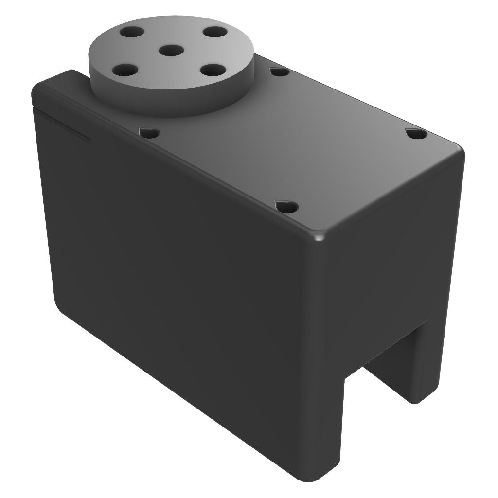
Servo 2